Function
The software for this project implements the logic that makes the mask run: controlling fan speed and allowing the user to check battery level.
Block Diagram
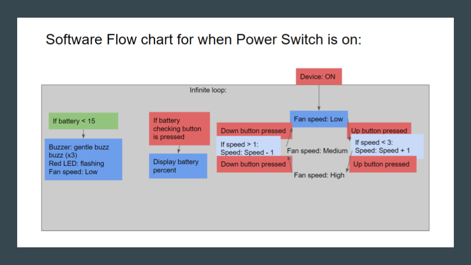
Shown here is the first draft block diagram to outline what the code needs to do. After a few optimizations, the control flow was updated to the flow chart below.
Flow Chart
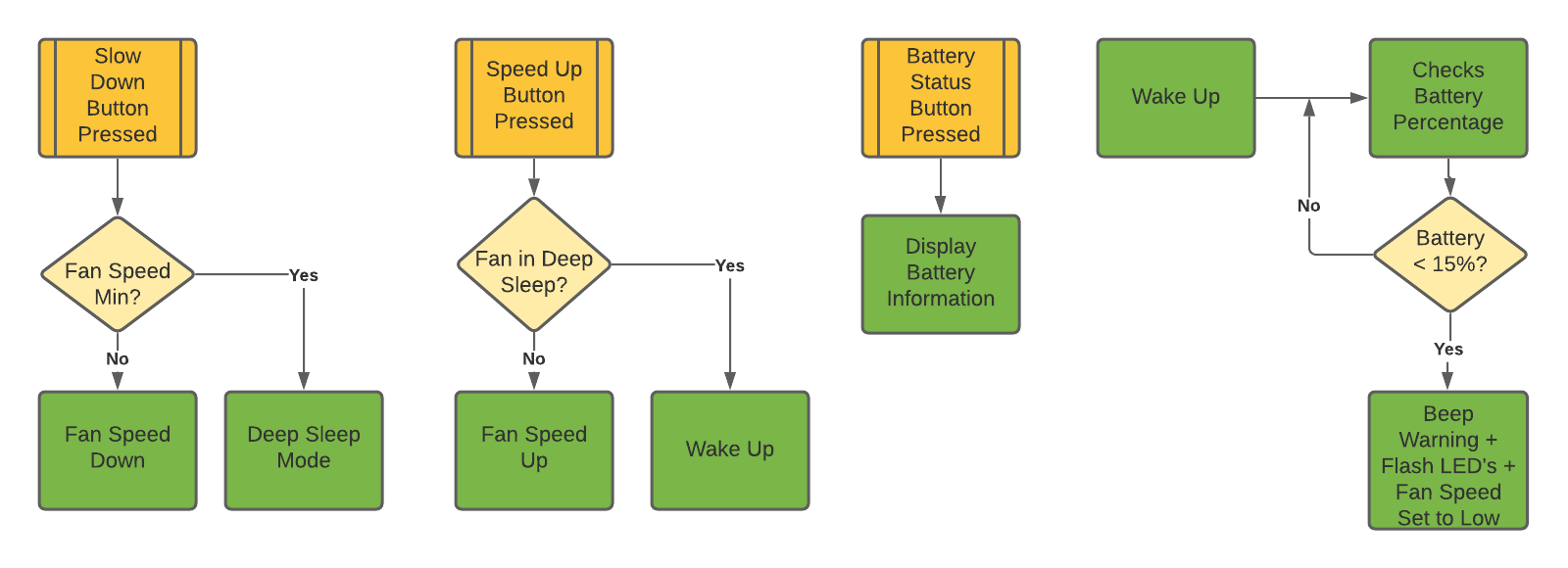
A notable feature is the conservation of power by utilizing hardware interrupts. Rather than the program constantly checking if the increasing and decreasing speed buttons are pressed, a hardware interrupt executes an action (in this case, changing fan speed) only when requested by a button push.
LED Battery-Level System
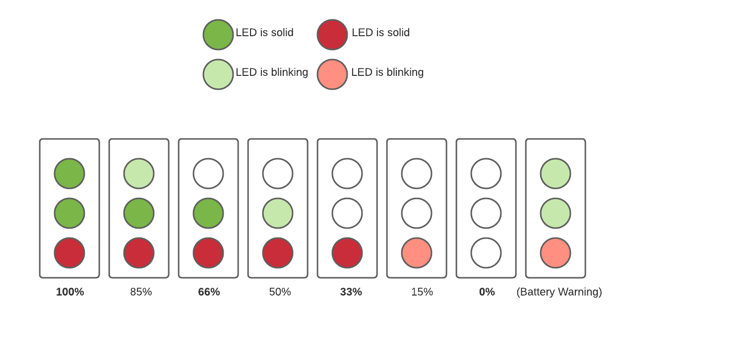
After much consideration, it was determined that battery level would be displayed through 3 LEDs, as shown above.
The LEDs are coded to maximize information about the battery through 3 states: on, blinking, or off. This allows for an intuitive display - the 8 states on the figure inform the user of a fairly accurate battery reading at a glance.