Schematics
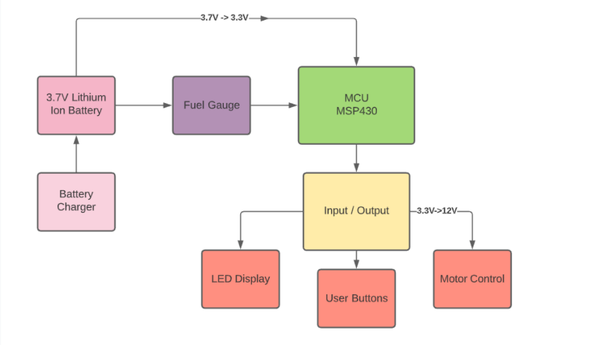
Top Level Diagram
Microcontroller
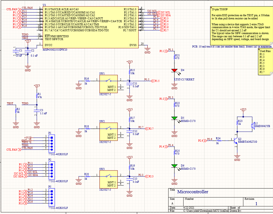
The MSP430 was chosen because it matched our price point and was readily available which allowed us to keep our design affordable and accessible. It supports low power mode which will be used to prolong the battery life.
We used the GPIO pins for buttons to gather user input, LEDs and a buzzer to provide a response, and the rest to handle communication between the MSP430 and the different components and on our pcb.
List of Parts
- 6x 1K OHM RESISTOR
- 1x 47K OHM RESISTOR
- 3x 10K OHM RESISTOR
- 1x 470 OHM RESISTOR
- 3x 5HEADER PINS
- 1x 10UF CAP
- 6x .1UF CAP
- 1x 1100PF CAP
- 1x RED LED
- 2x GREEN LED
- 1x TI MSP430G2553
- 1x Piezo Buzzer
- 3x TACTILE SWITCH
- 1x BJT TRANSISTOR
Battery Control
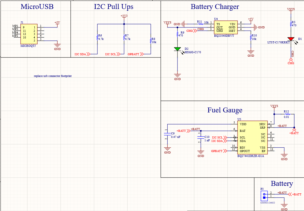
We used a fuel gauge circuit to determine how much charge is remaining in the battery. This essentially measures the current flowing through a small resistance resistor which determines the battery level and whether it needs to be recharged. It uses I2C communication protocol to communicate with the Microcontroller. As a result, we need Pull Up resistors to drive the I2C pins to high, which allows the Microcontroller to pull the SDA line down when it requests information.
List of Parts
- 1x IC FUEL GAUGE
- 1x IC BATTERY CHARGER
- 1x USB CONNECTOR
- 1x 2HEADER PIN
- 1x GREEN LED
- 1x RED LED
- 3x 10K OHM RESISTOR
- 2x 470 OHM RESISTOR
- 2x 4.7K OHM RESISTOR
- 1x .01 OHM RESISTOR
- 1x .47UF CAP
- 1x 1UF CAP
Power Control
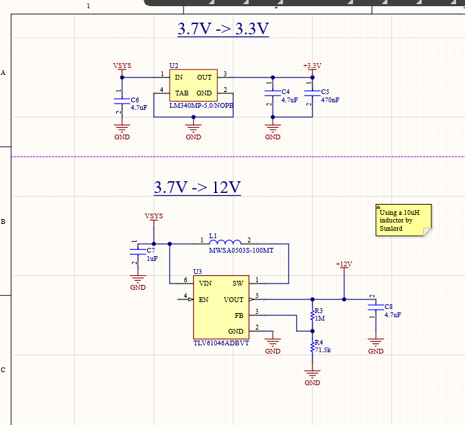
The microcontroller requires 3.3V to power, so as a result, we used an LDO (linear voltage regulator) to step down the 3.7 battery voltage to the necessary 3.3V .
We needed a boost converter, shown here, to step up the 3.7V to the 12V necessary to power our fan.
List of Parts
- 1x IC BOOST CONVERTOR
- 1x IC LDO
- 2x 1K OHM RES
- 1x 1UF CAP
- 1x 470NF CAP
- 3x 4.7UF CAP
- 1x 10UH INDUC
Motor Control
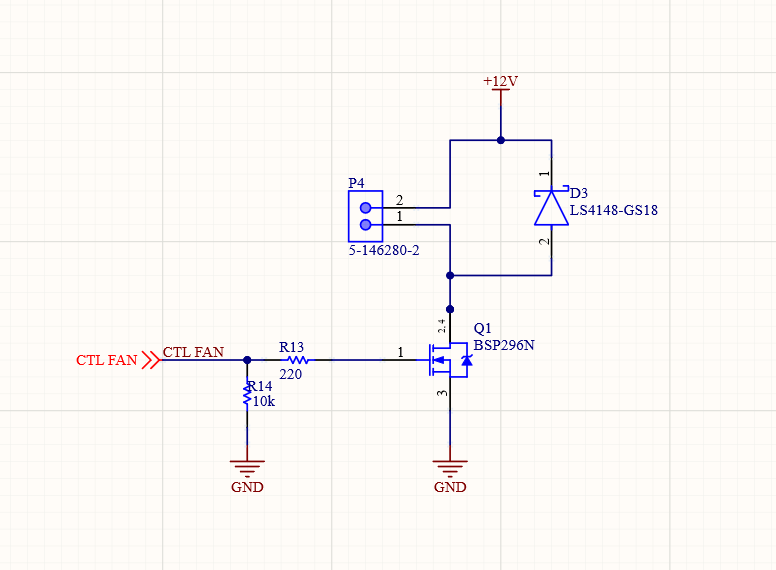
This motor circuit allows us to control the fan speed using Pulse Width Modulation which can be adjusted using a Microcontroller. A higher duty cycle allows more power to the fan, while the opposite holds true for a lower duty cycle.
List of Parts
- 1x 10K OHM RESISTOR
- 1x 220 OHM RESISTOR
- 1x Diode